Alumina ceramics: the "performance king" in the industrial field
In the landscape of modern industrial manufacturing, high-performance materials are the core driving force for equipment upgrades and process innovation. Among them, Alumina Ceramics, with their superior comprehensive performance, have become key materials in high-end fields such as semiconductors, new energy, automation equipment, and electronics, with market demand continuously rising. As a specialized enterprise providing industrial ceramic solutions, Dongguan Xinzhida Technology Co., Ltd. has been deeply involved in the R&D, production, and global supply of alumina ceramic components. With its precise control over material properties and professional services in the export sector, it has become a trusted alumina ceramic solution partner for overseas customers.
Alumina ceramics are special ceramic materials made from high-purity alumina (Al₂O₃) as the main raw material, formed and sintered at high temperatures. Based on the alumina content, they can be divided into different grades such as 95%, 99%, and 99.5%, with different purities suitable for different industrial scenarios. Compared with traditional metal materials and ordinary ceramics, the advantages of alumina ceramics extend throughout their entire lifecycle—production, use, and maintenance. Dongguan Xinzhida Technology is able to translate these advantages into tangible value tailored to the actual needs of overseas customers, becoming an important support for the upgrading of global industrial manufacturing.
1.Ultimate wear and damage resistance, significantly extending equipment lifespan
Industrial equipment operates under conditions of high speed, high-frequency friction, and strong particle abrasion, making core components highly susceptible to wear. This not only increases maintenance frequency but also affects production stability. Alumina ceramics boast a Mohs hardness of 9, second only to diamond, far exceeding stainless steel, carbon steel, and other metal materials. They also possess excellent wear resistance, with a wear resistance 10-20 times that of manganese steel and 5-10 times that of ordinary ceramics.
Dongguan Xinzhida Technology precisely formulates its alumina material based on the wear requirements of different industrial scenarios: For high-friction scenarios in automated equipment and mining machinery, 95% high-purity alumina is used to enhance the wear resistance of components, suitable for long-term high-intensity operation; for low-wear scenarios in semiconductor equipment and precision instruments, 99.5% alumina is selected, achieving zero wear at the micron level and avoiding impurity generation. Compared to generic products from ordinary manufacturers, Xinzhida's alumina ceramic accessories can extend the lifespan of core equipment components by 3-5 times, significantly reducing maintenance costs and downtime losses for overseas customers. This is the core reason for the long-term cooperation between many customers in Europe, America, and Southeast Asia.
2.High temperature and impact resistance, adaptable to extreme industrial environments
High temperatures and rapid heating/cooling are common conditions in industrial manufacturing. Ordinary materials are prone to softening, deformation, and cracking. Alumina ceramics, however, with their extremely high heat resistance (up to 1600℃ and above) and excellent thermal shock resistance, have become the core material choice for extreme environments. Their stable thermal conductivity and low coefficient of thermal expansion allow them to maintain dimensional stability even at high temperatures, without deformation or cracking due to temperature changes.
In scenarios such as new energy battery manufacturing, high-temperature furnaces, and heat treatment of automotive parts, the high-temperature resistance of alumina ceramic components is particularly prominent. Dongguan Xinzhida Technology has customized alumina ceramic screws, nuts, washers, and other products for high-temperature applications. Through precision sintering processes, they ensure that the products maintain stable mechanical properties and connection strength even at temperatures above 1200℃, without loosening, oxidation, or deformation. Compared to metal components, their alumina ceramic products can be directly adapted to high-temperature conditions without the need for additional heat insulation or protective devices, simplifying equipment structure and improving production safety.
3.Outstanding insulation performance, building a solid safety line in the electronics field
As electronic devices become increasingly miniaturized and highly integrated, the requirements for insulating materials are becoming increasingly stringent. Alumina ceramics possess excellent electrical insulation, dielectric strength, and dielectric properties, with a volume resistivity as high as 10¹⁴-10¹⁶ Ω·cm and a dielectric strength of 15-20kV/mm. Furthermore, they maintain stable insulation characteristics even under high-frequency and high-voltage environments, preventing safety hazards such as leakage and breakdown. They are perfectly suited to the needs of electronic appliances, semiconductor equipment, and high-voltage power equipment.
Dongguan Xinzhida Technology focuses on developing high-purity alumina ceramic components to meet the high-precision and high-safety requirements of the electronics field. From raw material selection to production processing, purity is strictly controlled throughout: alumina ceramics with a purity of 99% or higher offer more stable insulation performance, making them suitable for core insulating components in high-voltage semiconductor equipment and precision electronic instruments. For high-frequency communication equipment scenarios, the dielectric constant of the products is optimized to reduce signal transmission loss and ensure equipment operational stability. Currently, its alumina ceramic insulation components are supplied in bulk to electronic manufacturing companies in Europe and Southeast Asia, becoming a core material supplier for the upgrading of local electronic equipment.
4.Corrosion-resistant and anti-aging, suitable for complex industrial conditions
Equipment in chemical, pharmaceutical, and marine engineering fields is frequently exposed to acids, alkalis, salt spray, and corrosive media. Traditional metal materials are easily corroded and aged, seriously affecting equipment lifespan and production safety. Alumina ceramics possess extremely strong chemical stability, resisting acid, alkali, and salt spray corrosion. They do not react with most chemical media and are not prone to aging or performance degradation with long-term use, allowing for stable operation in complex corrosive environments.
Dongguan Xinzhida Technology Co., Ltd. customizes alumina ceramic cable shells, protective covers, and connectors to meet the corrosion resistance needs of chemical and pharmaceutical equipment. Through refined surface treatment, the products' corrosion resistance is enhanced, allowing direct contact with media such as hydrochloric acid, sulfuric acid, and medical disinfectants without corrosion, flaking, or breakage. Compared to organic materials such as plastics and rubber, alumina ceramic products are more resistant to high temperatures and aging, exhibiting more stable performance over long-term use, making them the preferred supplier of corrosion-resistant components for overseas chemical and pharmaceutical companies.
5.Lightweight and High-Precision: Facilitating Lightweight Equipment Upgrades
In fields such as new energy vehicles, drones, and precision instruments, lightweighting is crucial for improving performance and reducing energy consumption. Alumina ceramics, with a density of only 3.6-3.9 g/cm³, are significantly lower than metals like stainless steel (approximately 7.9 g/cm³) and carbon steel (approximately 7.8 g/cm³), while achieving micron-level (±0.005 mm) machining precision, perfectly balancing the demands for both lightweighting and high precision.
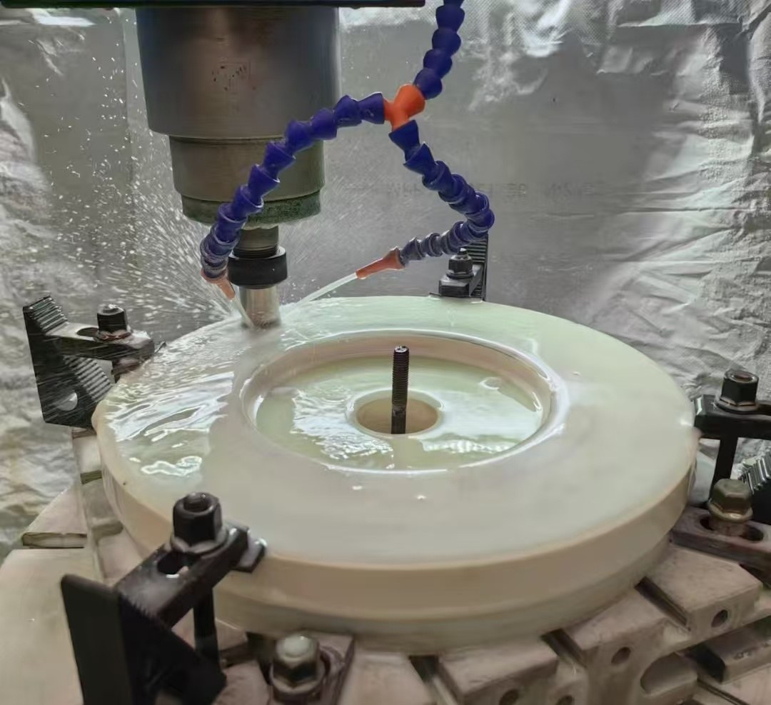
Dongguan Xinzhida Technology, leveraging precision machining technology, can process Alumina Ceramic Components into various complex shapes to meet the customized needs of lightweight equipment: providing alumina ceramic connectors for lightweight components in new energy vehicles, reducing component weight by over 30% while maintaining connection strength; and providing alumina ceramic support and transmission components for drones and precision instruments, achieving lightweight upgrades and improving endurance and operational sensitivity. Its lightweight Alumina Ceramic Parts have become a core component choice for many overseas high-end equipment manufacturing companies.
Dongguan Xinzhida Technology has been deeply involved in the industrial ceramics export sector for many years, understanding the core needs of overseas customers regarding product quality, delivery time, and after-sales support. We have built a comprehensive export service system, transforming our material advantages into customer value:
1.Customized solution matching: based on customer equipment drawings, usage scenarios, and performance requirements, we accurately recommend suitable alumina ceramic material grades and processing solutions, avoiding "using oversized materials" or "performance inadequate";
2.Flexible minimum order quantity and Fast Delivery: we support small-batch customization starting from 500 pieces. Regular products are readily available and shipped quickly. The delivery cycle for customized products is 50% shorter than industry giants, adapting to the multi-batch, small-volume procurement needs of overseas customers;
3.End-to-End quality sssurance: each batch of products undergoes multiple processes including dimensional inspection, density testing, wear resistance verification, and insulation performance testing, with third-party testing reports issued to ensure product quality meets international industrial standards;
4.Dedicated overseas team support: we have assembled a team proficient in international procurement rules and multilingual services, providing end-to-end services from product selection and solution design to customs clearance, logistics, and after-sales technical support, solving the procurement pain points of overseas customers.