Why Choose Lithium Batteries for Solar Energy Storage Systems?


In recent years, the popularity of solar energy has surged, with individuals and businesses alike turning to renewable energy to reduce their carbon footprint and energy costs. One essential component of a solar energy system is the energy storage solution, which ensures that excess energy generated during the day can be used when the sun is not shining. Among the various battery technologies available, lithium batteries have become the preferred choice for solar energy storage systems. But what makes lithium batteries stand out? Here are some key reasons:


1. High Energy Density

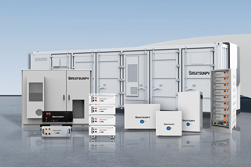
Lithium batteries offer a higher energy density compared to traditional lead-acid batteries. This means that they can store more energy in a smaller and lighter package. For homeowners or businesses with limited space, lithium batteries are an ideal option since they require less space for installation while still providing the necessary energy storage capacity.


2. Longer Lifespan

One of the most significant advantages of lithium batteries is their long lifespan. While traditional lead-acid batteries typically last around 3-5 years, lithium-ion batteries can last 10-15 years, depending on usage and maintenance. This longevity translates into long-term cost savings, as the need for replacement batteries is significantly reduced.


3. Higher Efficiency

Lithium batteries are more efficient in both charging and discharging. They have a higher charge/discharge efficiency compared to lead-acid batteries, meaning they lose less energy during the process. This efficiency ensures that more of the solar energy you generate is effectively stored and utilized, making the overall solar system more effective.


4. Faster Charging and Discharging

Lithium-ion batteries charge and discharge faster than other battery types. This is especially beneficial for solar energy systems that need to quickly store excess energy during the day and release it when needed, such as during periods of high energy demand or at night. Faster charging means that the system can be ready for use again in a shorter time frame.


5. Compact and Lightweight

Lithium batteries are significantly lighter and more compact than traditional lead-acid batteries. This makes installation easier and more flexible, especially in locations where space is limited. Whether on rooftops or inside buildings, the compact nature of lithium batteries allows for a more efficient use of available space.


6. Better for the Environment

Lithium batteries are also considered more environmentally friendly than traditional lead-acid batteries. They contain fewer harmful materials, and the process of recycling lithium-ion batteries is more straightforward. This makes lithium batteries a more sustainable choice in the long run, aligning with the green energy goals of solar power systems.


While lithium batteries tend to have a higher upfront cost compared to traditional lead-acid batteries, their numerous benefits—such as longer lifespan, higher efficiency, and reduced environmental impact—make them an excellent choice for solar energy storage. As solar power adoption continues to rise, investing in lithium-ion batteries for your energy storage needs is a smart, forward-thinking decision.
What are the types of press brake tooling (bending machine molds )

Classification of commonly used press brake tooling:

There are several types of bending tools, including L-shaped, R-shaped, U-shaped, Z-shaped, etc. The upper punch mainly has different angles such as 90 °, 88 °, 45 °, 30 °, 20 °, and 15 °. There are double and single slots with different slot widths of 4-18V in the lower dies, as well as R lower mold, acute angle lower mold, flattening tool set, etc. press brake tooling punch and die are divided into sections and whole parts: the upper punch is generally divided into sections of 300mm, 200mm, 100mm, 100mm, 50mm, 40mm, 20mm, 15mm, 10mm, and the whole is 835mm. The lower die is generally divided into sections of 400mm, 200mm, 100mm, 50mm, 40mm, 20mm, 15mm, and 10mm, and the whole is 835mm.

Bending tools are made of steel that has undergone special heat treatment, and have the characteristics of high hardness, low wear, and high pressure resistance. However, each set of molds has its maximum pressure capacity: tons/meter. Therefore, when using the mold, the length of the mold should be selected, that is, how much pressure should be added per meter, and it must not exceed the pressure marked by the mold.

② In order to avoid damaging the mold, we have stipulated that when aligning the origin, upper and lower molds with a length of at least 300mm must be used to align the origin Only after aligning the origin can the upper and lower molds of the same height be used. It is strictly prohibited to use split molds for the origin, and the origin must be based on the internal origin pressure of the AMADA machine.

③ When using molds, due to the different heights of various molds, only molds of the same height can be used when selecting molds on a machine, and molds of different heights cannot be used.

④ When using molds, appropriate upper and lower molds should be selected based on the hardness, thickness, and length of the metal sheet material. Generally, the lower mold is used according to the standard of 5-6T, and the length should be longer than the sheet material. When the material is harder and thicker, a lower mold with a wider groove should be used.

⑤ When bending sharp angles or pressing dead angles, a 30 degree angle should be selected, with the sharp angle bent first and the edge pressed dead later. When bending the R angle, the R upper mold and R lower mold should be selected.

⑥ When bending longer workpieces, do not use segmented molds to reduce tool indentation, and choose single groove ones because the outer angle R of the V-groove of the lower mold of the single groove is large, which is not easy to produce bending indentation.

⑦ When selecting the upper mold, we should understand the parameters of all molds and decide which upper mold to use based on the shape of the product to be formed.

⑧ When bending products with extremely hard hardness or thick sheet metal, it is not allowed to use molds to bend steel bars or other cylindrical products.

⑨ When using molds, one should have a clear mind and lock the upper and lower molds after the machine has aligned with the origin. Do not let the molds fall off, injure people or damage the molds. During the operation, be careful not to apply too much pressure at once and pay attention to changes in the displayed data on the screen.

⑩ After using the tools, it should be promptly returned to the tools storage cabinets rack and placed according to the markings. The dust on the mold should be regularly cleaned and rust proof oil should be applied to prevent rusting and reduce the accuracy of the mold.

The schematic diagram of the shape of the upper punch type is mainly used for processing angles greater than or equal to 90 with a straight knife as shown in the following figure, and for processing angles greater than or equal to 90 with a curved knife as shown in the following figure. For processing angles greater than or equal to 30 with a sharp knife as shown in the following figure

The schematic diagram of the shape of the lower die type is mainly used. Note that the single V lower mold is shown in the following figure. 1. When the V-shaped angle is 86 (reference value), angles greater than or equal to 90 can be processed. 2. When the V-shaped angle is 30 (reference value), angles greater than 30 can be processed. The lower mold used for the quick bending machine is of this type. The double V lower mold is shown in the following figure. The lower mold used for AMADA bending machine is of this type

Segmentation of bending tools:

Under normal circumstances, the length of the tool is 835mm; to facilitate bending different lengths, the entire length of the tool is often divided into the following sections: 10+15+20+40+50+100+100+200+300=835

The correspondence between plate thickness and groove width:

Normally, the slot width is 6 times the thickness of the board. The comparison table of plate thickness and groove width currently specified by Wan Jiayuan is as follows: Material thickness (mm) 1.01.21.52.02.5 Bending machine lower die width (mm) 6681216

The minimum bendable size for processing according to the comparison table above (including plate thickness):

Plate thickness (mm) 1.01.21.52.0L minimum size for L-shaped bending (mm) 4.54.768.5Z minimum size for Z-shaped bending (mm) 77.4912


Conventional bending sequence:

1. Short side first and then long side: Generally speaking, when all four sides are bent, folding the short side first and then the long side is beneficial for the processing of the workpiece and the assembly of the bending mold

2. First the periphery and then the middle: Normally, it is folded from the periphery of the workpiece to the center of the workpiece

3. Partial first and then overall: If there are some structures inside or outside the workpiece that are different from other bends, it is generally necessary to bend these structures first and then bend other parts

4. Consider interference situations and arrange the bending sequence reasonably: The bending sequence is not fixed, and the processing sequence should be adjusted appropriately according to the shape of the bending or obstacles on the workpiece


The Ultimate Guide to Scaffolding Pipe Load Capacity Safety, Standards, and Structural Integrity

The structural soundness of temporary support systems is unarguably one of the most important factors to consider when working on large-scale construction and industrial infrastructure. Within every scaffolding system, there are pipes used for support. Knowing what size and weight capacity your scaffolding pipe will be able to safely hold is critical to providing safe work environments, maximising your material utilised on-site, and achieving compliance with the international engineering standards.

This guide outlines exactly what things are taken into consideration when determining how much weight each type/size of scaffold metal pipe can safely support, as well as what standards exist to govern the use of scaffolding pipes in all parts of the world.


1. The Fundamentals of Load Capacity


How much weight can be supported by the scaffolding pipe? The Load Capacity is found by determining how much load (force) a given scaffolding pipe can bear before it reaches its Limit-State of being permanently deformed or physically collapsing. In the professional Engineer aspect of your job, this value is always calculated in relation to all other pipes in a given scaffolding grid; this means you cannot just use this value by itself.

Dead Loads vs. Live Loads

  • Dead Loads: The self-weight of the scaffolding structure (i.e., the weight of the pipes, steel planking, steps, and couplings that make up the actual scaffolding).
  • Live Loads: The combined weight of all persons, equipment, and materials being stored on the scaffolding framework.


2. Key Determinants of Structural Strength


The load-bearing potential of a scaffold tube is dictated by several physical and mechanical properties.

A. Specification of Material and Thickness of Wall:

  • The material most often used for structural scaffolding is galvanised carbon steel, and the thickness of the wall (typically 3.2mm or 4.0mm) has a direct impact on how much bending moment the pipe can withstand. A thicker wall gives an increase in the cross-section of the pipe and therefore gives an increase to the axial load bearing capacity.

B. The Slenderness Ratio and Buckling:

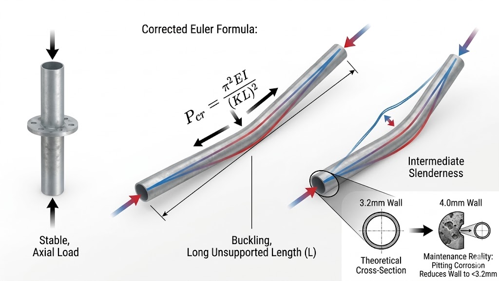
  • As the unsupported length of a pipe increases, the strength of the pipe decreases due to being slender. This is referred to as the slenderness ratio in engineering. A pipe may be made from a strong material, but if the vertical lift height between the two horizontal ledgers is too great, the pipe could buckle when loaded to less than its theoretical crushing load.

C. Regulatory Standards: EN39 and BS1139

Compliance with international standards ensures consistency in performance.

  • Our commercial and technical stock includes conventional steel tubes to BS1139 / EN39. These are available in straight lengths and have a nominal outside diameter of 48.3mm with a diameter tolerance. The steel has a minimum specified yield strength of 235 N/mm2. The use of these components as a base for safe load calculations is a common starting point.


3. Load Classes and Duty Ratings


Scaffolding systems are classified based on their intended application. These classifications dictate the maximum Uniformly Distributed Load (UDL) allowed on the working platforms.


Load Class

Rated Capacity (UDL)

Application Profile

Class 1 (Extra Light)

0.75 kN/m2

Inspection and very light maintenance.

Class 3 (General Purpose)

2.00kN/m2

General construction and bricklaying.

Class 4 (Heavy Duty)

3.00kN/m2

Masonry, concrete work, and heavy loading.


4. Engineering Calculations for Load Capacity


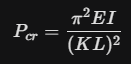
Calculating the critical load of a vertical scaffold standard (acting as a compression member) involves assessing Euler’s buckling formula.

The critical buckling load Pcr is expressed as:


Where:

E: Modulus of elasticity of the steel.

I: Second moment of area.

L: The actual length of the pipe.

K: The effective length factor (dependent on how the ends are secured).


The Safety Factor: To account for unpredictable variables such as wind oscillation or minor material defects, a safety factor (typically 4:1) is applied to the ultimate breaking load to determine the Safe Working Load (SWL).


5. Factors That Diminish Load Capacity


Theoretical capacity must be adjusted for real-world conditions. Over time, several factors can compromise the integrity of the steel:

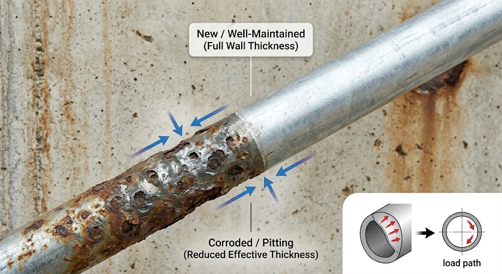
  • Corrosion/Oxidation: When deep rust is present on the pipe, the effective thickness can be greatly reduced to the point where, for both static and dynamic loads, the pipe's inertia can be dramatically decreased.
  • Eccentric Loading: An eccentric loading is defined as a loading where the center of loading is not directly above the center of the pipe. In this type of loading, there is an additional bending stress imposed on the pipe. This changes the point of failure from the hoop stress break point to the bending stress break point.
  • Physical deformation: Dents, bends, and 'straightened' pipes cannot be repaired and should be taken out of service as they will not have met the original performance criteria.


6. Practical Implementation for Site Safety


To maintain the highest standards of structural integrity, consider the following technical practices:

  • Uniformity of Materials: Avoid mixing tubes of different wall thicknesses (e.g., 3.2mm and 4.0mm) within the same vertical run to ensure predictable load distribution.
  • Rigid Coupling: Ensure all couplers are torqued to the manufacturer’s specifications, as the "fixity" of the joints affects the $K$ factor in buckling calculations.
  • Regular Verification: Conduct periodic thickness testing and straightness checks to ensure that the inventory still meets the original mill certificate specifications.


Conclusion


Determining scaffolding pipe load capacity is a balance of material science and mechanical engineering. By adhering to recognized standards like BS1139 and EN39, and factoring in variables like slenderness ratios and safety margins, construction projects can proceed with the highest level of structural confidence.

Safety in scaffolding is not a matter of guesswork—it is a matter of calculated precision.


Ensure your next project is built on a foundation of certified strength. We provide premium, high-strength scaffolding pipes and components that exceed international safety standards.

Contact us today to receive full technical specifications and mill certificates for your scaffolding requirements!


FAQ


1. What is the standard load capacity of a 48.3mm scaffold tube?

  • The load capacity of a standard 48.3mm outside diameter (O.D.) scaffold tube depends primarily on its wall thickness and its unsupported length. For a standard 4.0mm wall thickness steel pipe complying with EN39, the safe axial load is typically around 40 kN to 60 kN, provided the unsupported height (lift) is kept within standard limits (usually 2.0 meters). However, this value decreases significantly as the lift height increases due to buckling risks.


2. How does wall thickness (3.2mm vs. 4.0mm) affect load-bearing?

  • Wall thickness is a critical factor in structural stability. A 4.0mm pipe has approximately 20% more steel than a 3.2mm pipe. This extra material significantly improves the Radius of Gyration and the Moment of Inertia, making the 4.0mm pipe much more resistant to buckling. In heavy-duty applications or high-clearance structures, 4.0mm pipes are the industry preference to maintain a higher safety margin.


3. Can rusted or corroded pipes still meet load requirements?

  • Corrosion is a "capacity killer." Surface rust (flash rust) typically doesn't affect structural integrity, but pitting corrosion or internal scaling reduces the effective wall thickness. If a pipe’s wall thickness has decreased by more than 10% from its original specification, it should be downgraded or decommissioned, as it can no longer reliably meet the load capacities defined in standards like BS1139.

Tired of Picking from Static Shelves? Discover the Flow of Efficiency.

Is your order picking process slowed down by reaching, searching, and shuffling boxes? Do you struggle with inventory rotation, leading to expired stock? It’s time to replace static storage with dynamic movement. Carton Flow Racking isn't just shelving; it's a gravity-powered logistics system designed for speed and accuracy.

What is Carton Flow Racking and How Does It Work?

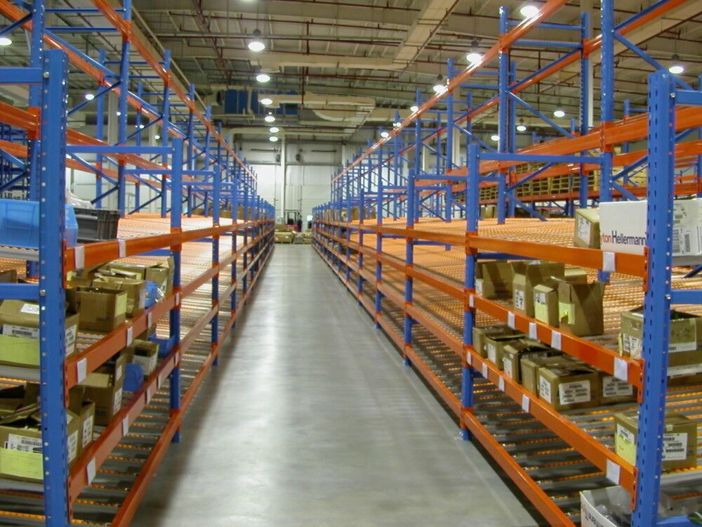
Carton flow racking is a high-density, dynamic storage system where boxes or cases glide on rolling tracks from the loading point at the rear to the picking face at the front. It turns traditional shelving into a first-in, first-out (FIFO) conveyor system powered by gravity.

The principle is elegantly simple and highly effective:

Gravity-Powered Movement: Each shelf lane is inclined and fitted with low-friction wheel or roller tracks. When a carton is loaded into the back of a lane, gravity gently pulls it forward.

Automatic Product Rotation: As the front carton is picked, the next one immediately rolls into position. This guarantees perfect FIFO inventory rotation, eliminating the risk of stock becoming obsolete at the back of a deep shelf.

High-Density Storage: The system allows for deep lane storage (often 5-10 cartons deep) while maintaining instant access to the front item. This dramatically increases storage density compared to single-depth shelving and reduces the aisle space required.

Where Is Carton Flow Racking the Ideal Solution?

This system revolutionizes operations in any environment with a high volume of case-picking for fast-moving goods. It is the gold standard for:

E-commerce & Retail Distribution Centers: Perfect for picking individual SKUs for direct-to-consumer orders or store replenishment.

Pharmaceutical & Medical Supply Warehouses: Ensures strict FIFO rotation for products with expiration dates or lot tracking requirements.

Cosmetics & Consumer Goods Logistics: Ideal for handling a vast number of SKUs in standard-sized cartons.

Food & Beverage Distribution: Excellent for managing perishable goods and high-turnover packaged products.

Assembly Line Kitting & Parts Supply: Keeps components organized and automatically presented to assembly workers.

Why Choose Kingmore Carton Flow Racking?

At Kingmore Storage Equipment Manufacturing, we engineer flow systems for reliability, not just movement. We understand that a jammed lane or a damaged track halts your entire operation.

Choosing Kingmore Carton Flow means investing in a system built with distinct competitive advantages:

Kingmore Precision-Engineered Tracks: We offer both heavy-duty roller tracks for rugged, uneven-bottom cartons and smooth wheel tracks for ultra-quiet, gentle handling of delicate packaging. Our tracks are manufactured with tighter tolerances for consistent, reliable flow without jamming.

Superior Load Capacity & Durability: Our tracks and supporting beams are constructed from high-grade steel with robust welds. They are designed to handle maximum loads without sagging, ensuring smooth flow even when fully loaded. This reduces long-term maintenance and downtime.

Smart, Adjustable Speed Control: Not all products flow the same. Kingmore systems feature easily adjustable speed controllers at the lane entry. By simply turning a dial, operators can set the perfect rolling speed—from gentle to fast—for any carton weight or size, preventing impact damage at the pick face.

Modular & Highly Configurable Design: Our system is fully modular. Lanes can be easily added, removed, or reconfigured. We provide lanes in multiple widths and depths, and our pick faces can be integrated with Kingmore's Labeling & Lighting Systems for error-proof picking.

Expert Throughput Analysis: Our team doesn't just sell racks; we analyze your SKU velocity, dimensions, and order profiles to design the optimal lane depth, slope, and layout to maximize your pick rates and storage density from day one.

Let Your Inventory Flow, and Watch Your Productivity Soar

Stop wasting time walking and searching. Transform your picking area into a dynamic, high-throughput zone with carton flow racking from Kingmore Storage Equipment Manufacturing.

Ready to automate your picking with gravity? Contact Kingmore today for a workflow analysis and see how our reliable carton flow solutions can accelerate your order fulfillment cycle.

How to Choose the Right Industrial Blades 5 Key Factors to Extend Tool Life and Reduce Costs?

In the world of high-speed manufacturing, whether you are processing seafood, printing packaging, or recycling plastic, your blades are the heartbeat of your production line. A dull or incorrectly selected blade doesn't just produce poor-quality cuts—it causes machine downtime, increased waste, and skyrocketing maintenance costs. At Ma'anshan Guangchuan, we understand that the right blade is an investment in efficiency. In this guide, we share professional insights on how to choose the perfect blade for your application.


1. Match the Material to Your Application

The first step in blade selection is understanding the material being cut.

  • Food Processing: For products like shrimp deveining or meat dicing, stainless steel with high corrosion resistance is essential to meet food safety standards.

  • Abrasive Materials: When shredding waste or recycling rubber, tools require high-impact alloy steel or tungsten carbide to withstand extreme wear.

  • Paper & Film: Slitting applications require high-speed steel (HSS) to maintain a razor-sharp edge over millions of rotations.


2. Consider the Hardness (HRC) Balance

Hardness is a double-edged sword. While a harder blade (higher HRC) stays sharp longer, it also becomes more brittle.

  • High Hardness: Best for thin films and soft materials to ensure clean, burr-free edges.

  • Balanced Toughness: Essential for heavy-duty shearing or shredding where the blade must absorb impact without chipping.


3. Precision Matters: The Role of CNC Grinding

A blade is only as good as its finish. Using advanced CNC grinding machines, such as the MKP7140 used in our facility, ensures micron-level flatness and edge consistency. A smoother surface finish reduces friction and heat buildup, which are the primary enemies of blade longevity.


4. Geometry and Edge Angle

The "bevel" or angle of the blade edge significantly impacts performance.

  • Acute Angles: Provide the cleanest cuts but are more delicate.

  • Large Angles: Offer more support behind the edge, making them ideal for heavy-duty metal shearing or wood chipping.


5. Professional Packaging and Anti-Rust Protection

Often overlooked, how a blade is stored and shipped affects its initial performance. High-precision tools should arrive in reinforced, sea-worthy wooden crates with anti-rust oil application. At Guangchuan, we utilize heavy-duty wooden crate packaging to ensure your precision edges remain pristine during global transit.


Choosing the right industrial blade is a balance of material science, precision engineering, and application knowledge. By investing in quality tools, you reduce the "Total Cost of Ownership" by minimizing blade changes and maximizing output.

VFD System Module Guide Understanding the Roles of Siemens 6GK7342-5DA02-0XE0 and 6ES7153-4AA01-0XB0

In a VFD (Variable Frequency Drive) control system utilizing Siemens automation components, the modules 6GK7342-5DA02-0XE0 and 6ES7153-4AA01-0XB0 serve distinctly different functions, and whether they are both required depends entirely on your system architecture.


 Do You Need Both?

Typically, you do not need both modules simultaneously for a standard application, as they operate in different network domains and physical locations .

- 6GK7342-5DA02-0XE0 (CP 342-5): This is a Communications Processor (CP) designed for the S7-300 PLC rack. Its primary role is to connect the central PLC controller to a PROFIBUS DP network . In a VFD system, you would use this module if your drives are connected via PROFIBUS and you need the central PLC to master the network and exchange data with the drives .

- 6ES7153-4AA01-0XB0 (IM 153-4 PN): This is an Interface Module (IM) for an ET 200M distributed I/O station . Its role is to connect remote I/O modules (mounted on a separate sub-rack) back to the central PLC via a PROFINET network . You would use this if your VFD system requires local sensors/actuators to be wired to a remote cabinet away from the main PLC.


 Key Functions:

- CP 342-5 (PROFIBUS DP): Acts as the master or slave on a PROFIBUS network. It handles communication with drives, HMIs, or other field devices, offloading this task from the CPU .

- IM 153-4 PN (PROFINET IO): Acts as the gateway for an ET 200M remote I/O rack. It allows standard S7-300 I/O modules to be placed remotely and communicate with the controller over an industrial Ethernet (PROFINET) network .

6ES7 153-4AA01-0XB0

 Critical Usage Considerations

1.  Network Architecture: Do not confuse their purposes. A CP 342-5 is for the central controller rack; an IM 153-4 is for a remote I/O rack. Using them together would imply a complex system with both PROFIBUS drives and remote PROFINET I/O.

2.  Product Lifecycle: Note that the specific model 6ES7153-4AA01-0XB0 has been announced for discontinuation (as of October 2023) . Verify the current status or consider successors for new designs.

3.  Installation & Safety: Both modules are sensitive to electrostatic discharge . Ensure proper grounding of the mounting rail . Always disconnect power before installation and maintain adequate clearance (at least 40mm) around modules for ventilation .